

- Nano-selective forward osmosis technology by SideStroem featured in Everything About Water - February 10, 2024
- SideStroem and Singapore Institute of Technology featured in AsianScientist - April 29, 2023
- SideStroem joins world class accelerator program - November 12, 2022
How do draw and feed streams circulate in an FO module?
Here are ForwardOsmosisTech’s answers to Jose’s questions
Is the membrane the same in RO than in FO?
No. Since the driving force in reverse osmosis processes is hydraulic pressure compared to osmotic pressure in forward osmosis processes, reverse osmosis membranes and forward osmosis membranes are inherently different. A good RO membrane is a poor FO membrane and vice versa. We have previously published a guide on forward osmosis membranes and membrane processes, which gives an introduction to the difference between RO and FO membranes.
What are the circulation paths for feed (raw water) and draw solutions inside spiral wound FO modules, plate and frame FO modules, and tubular FO modules?
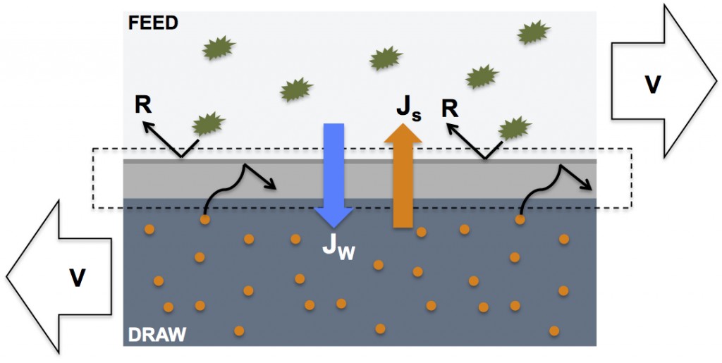
In general, forward osmosis processes require flow (typically cross flow) of draw and feed solutions on either side on the forward osmosis membrane. This requirement is the same in modules with varying geometric form factors.
Sterlitech have made a useful animation showing the counter current flow of feed and draw solutions in a forward osmosis test cell.
As for the flow path in different types of modules, I’m afraid we do not have any specific FO animations to help. Having said that, Hydranautics have made a useful animation on the flow paths in an RO spiral wound module. When viewing the animation try to imagine the permeate side being replaced by a flowing stream of draw solution; that’s pretty much how the flow path will be in a spiral wound forward osmosis module.