


.jpg)
Passionate about forward osmosis technologies and their commercial applications & adaptations.
- Forward osmosis is not dead – interview with leading water consultant Walid Khoury - August 30, 2020
- Listing of major commercial & academic FO players on ForwardOsmosisTech - April 12, 2020
- 0.26MGD FO-SWRO Hybrid for seawater desalination achieves 25% energy reduction compared to MF/SWRO - December 14, 2019
Q: What is a membrane?
In the context of the water treatment industry, a membrane is a thin, porous structure that can be used as a selective barrier between two aqueous solutions – allowing some molecules to pass through but not others. In most cases, the goal of water treatment membranes is to clean aqueous streams by removing pollutants in the form of suspended particles or dissolved solutes. Here, membrane selectivity is quantified by the membrane’s rejection to pollutants as solution travels through the membrane. Rejection values are largely determined by the average pore-size of the membrane’s selective layer (a membrane with a 1μm average pore-size rejection layer will allow molecules with sizes below 1μm to pass through and reject molecules with sizes above 1μm). The classical membrane filtration spectrum is summarized below:
| Filtration type | Typical rejection range (in size of pollutant) | Types of particles/molecules rejected |
| Microfiltration (MF) | 40nm to 3μm | Bacteria, paint pigments |
| Ultrafiltration (UF) | 3nm to 100nm | Proteins |
| Nanofiltration (NF) | 1nm to 6nm | Sugars, pesticides, and divalent ions |
| Reverse Osmosis (RO) | 1nm and below | Monovalent ions |
Data adopted from the Filtration Spectrum by GE Osmonics
Q. What is a forward osmosis membrane?
A forward osmosis membrane is a water treatment membrane capable of facilitating forward osmosis processes
FO membranes are a relatively new addition to the classical membrane filtration spectrum outlined above. The typical rejection ranges of FO membranes are comparable to tight nanofiltration (NF) membranes as well as reverse osmosis (RO) membranes.
Forward osmosis membrane performance
The performance of FO membranes is routinely quantified by the following parameters:
- Flow of water (measured in L/m2h – also written as LMH) from the low concentration side (the FEED side) to the high concentration side (the DRAW side)
- Reverse diffusion (measured in g/m2h – also written as GMH) of DRAW solutes from the DRAW side to the FEED side
- The rejection (measured in %) properties of the membrane towards molecules on the FEED side entering the DRAW side
Flow of water (Jw), reverse diffusion of draw solutes (Js), and rejection (R) are illustrated in the figure below. The FO membrane is indicated by a dashed rectangle and consists of thin rejection layer / active layer (dark grey) incorporated into an underlying porous support (light grey).
The active layer of an FO membrane must be sufficient at rejecting both molecules in the feed (green stars) and solutes in the draw (orange dots). The support layer must provide the FO membrane with mechanical stability and at the same time allow water and solutes to pass through with as little resistance as possible.
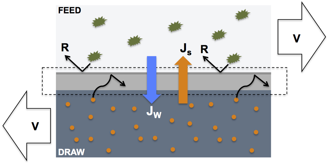
NB: When reporting the performance of FO membranes it is important to include information such as the chemical composition of feed and draw solutions, the cross flow velocity (V) of feed and draw solutions across either side of the membrane, the orientation of the membrane’s active layer (towards feed or draw), and if any hydrostatic pressure difference exists between the feed and draw solutions.
Forward osmosis membrane design
FO membrane processes are powered by an osmotic pressure difference between the low concentration feed solution on one side of the membrane’s active layer and the higher concentration draw solution on the reverse side of the active layer. The higher the osmotic pressure difference and the shorter the distance over which the gradient is maintained, the higher the water flux across the membrane. Hence, FO membrane performance is critically dependent on efficient diffusion of draw solutes into the support layer and support layer design is therefore one of the most important elements of the overall design of FO membranes.
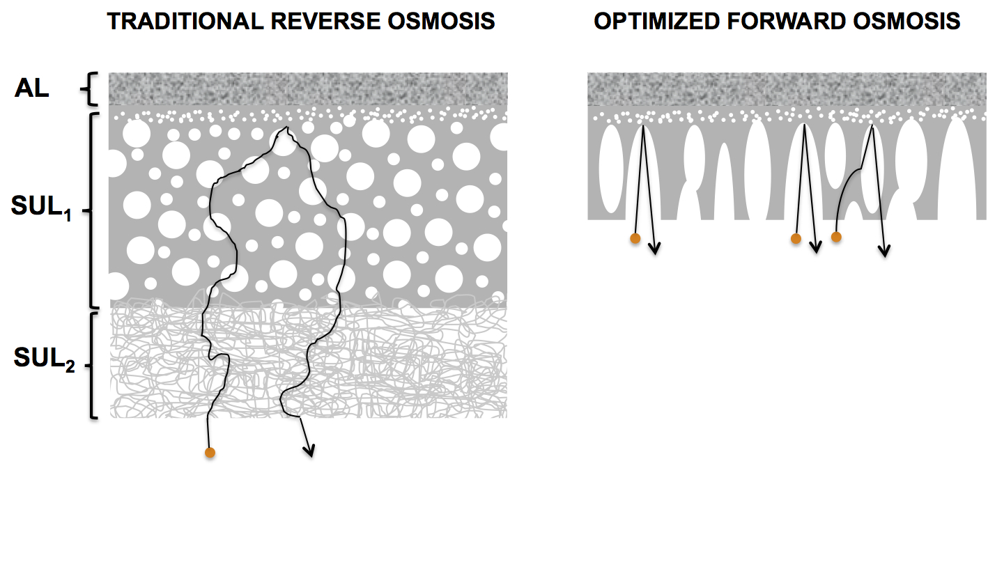
The effect of support membrane design on diffusion of draw solutes is illustrated in the figure below showing schematic membrane cross sections of traditional RO and optimized FO membranes. The figure demonstrates why traditional RO membranes make poor FO membranes. Since RO membranes facilitate water treatment through application of hydrostatic pressures, the membranes must have mechanical strength. The mechanical strength is typically achieved by sandwiching together a sponge-like upper support layer (SUL1 with a loose mesh (SUL2). Note that the upper support layer becomes denser towards the active layer (AL), which secures a smooth surface for active layer formation. It is easy to picture the difficulties draw solutes face when diffusing through the support layers of a traditional RO membrane.
FO membranes, on the other hand, do not have the same requirements for mechanical strength and can therefore make do with a single support layer. In addition, the FO membrane support layer can be thinner and have a more open pore structure compared to its counterparts in RO membranes. The reduced thickness combined with the change in pore structure enhances draw solute diffusion into the support layer thus greatly improving the FO performance.
For a great scientific resource on the relationship between support membrane structure and FO performance, check out:
Tiraferri et. al. , 2011 “Relating performance of thin-film composite forward osmosis membranes to support layer formation and structure”